Inverter end-of-line test bench (EOL) with transfer system

The project

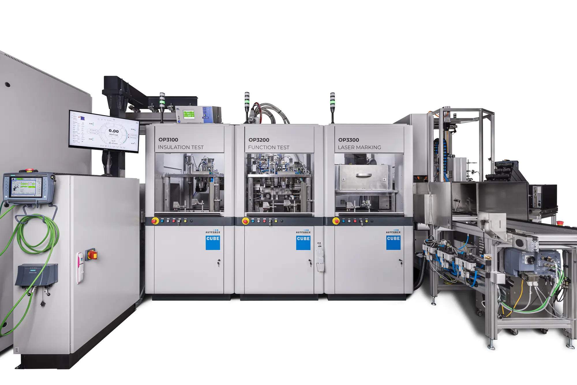
We were able to implement an end-of-line inverter test bench for our customer. The inverters (front axle and rear axle) for an electric vehicle are tested and then packaged. The following tests are carried out:

  • Dielectric strength and insulation resistance test
  • Inverter function test
  • Laser marking for component identification

In this project, component transportation was implemented using a transfer system. Alternatively, it would also have been possible to set up the entire test bench as a robot cell. Individual stations, such as the function test, can also be duplicated to cover a higher production volume.

Keyfacts

  • Cycle time: 182 seconds
  • Production throughput time: approx. 15 minutes
  • System availability: 95%
  • Plant output: 80,000 test objects / year
  • Parts / day: 342 pieces
  • Type variety: 2 types (front & rear axle)

Your added value with AUTFORCE

Increasing energy efficiency

The sophisticated energy recovery of our system not only optimizes the operating costs of the test bench, but also increases energy efficiency. This helps to minimize the total cost of ownership while ensuring sustainable and cost-efficient operation.

Reliable partner

As experienced experts with over 20 years of industry knowledge in the control of complex assembly lines and test benches in the automotive sector, we are your reliable partner. Our long history of success is testament to our commitment to the highest quality standards and customer care.

Gaining flexibility

Our autfactory test bench control system offers you the freedom to create your own test sequences without time-consuming programming. This flexibility allows you to adapt the test stand to your individual requirements and thus increase efficiency and productivity.

Comprehensive service from a single source

With us, you have a single point of contact for all your concerns – from the design of the plant to its complete acceptance. Our comprehensive service guarantees smooth project execution and ensures that your individual requirements and goals are always in focus.

Insulation test

Before the actual function test begins, we subject the modules and circuit boards of the inverter to a thorough insulation test. This test is carried out either at the beginning or end of the EOL test, as required. It is crucial to ensure that the product meets the highest standards. The following attributes are checked:

Dielectric strength of the assemblies: We check whether the assemblies meet the requirements for dielectric strength.
Flashover: Each circuit board is checked for flashover in order to detect possible defects at an early stage.
Potential sources of error: Potential sources of error, such as lost screws that could inadvertently land on the circuit board during the assembly process, are detected to prevent potential consequential damage.

Step 1

Step 2

Function test

The functional test is the decisive step in the EOL, which serves to ensure the quality of the manufactured product. Our approach ensures that the inverter is tested under real conditions. This applies not only to the direct current source (battery), but also to the motor side. The functional test includes a multitude of precise tests to ensure that the inverter meets the highest performance requirements. Some of them are:

    • Tempering: The inverter is tempered with a glycol-water mixture, just like later in the real vehicle.
    • Approach load points: The inverter is tested by approaching different load points to ensure performance in different operating scenarios (e.g.: operating points of maximum current or maximum losses).
    • Active / passive discharge: Both active and passive discharge are carefully monitored and evaluated to ensure that the safety circuits built into the inverter are effective.
    • Calibration of the current sensors: Precise calibration of the current sensors ensures that the measured currents can be accurately recorded and processed.
    • Blow out the remaining coolant to prepare the inverter for transportation.

Laser marking

In our fully automatic AUTFORCE CUBE, designed in the in-line version, each inverter passes through a laser marking station. This method ensures precise and permanent labeling of each product for optimum traceability. Laser marking includes essential information that enables clear identification and detailed traceability. This includes the DMC code, the serial number and the test results of the inverter.

Step 3

Step 4

Packaging station

In the final step, the semi-automatic packaging station, the inverters undergo final treatment to ensure that they are optimally protected and prepared for safe transportation.

    • Precise caps and labels for complete protection: The inverters are provided with caps and a label to ensure their identification and traceability. The operator attaches the cover caps manually, while sensors ensure that each cap has been fitted precisely.
    • Traceability label for complete traceability: Once all cover caps have been securely placed, a traceability label is printed and applied to the top cover of the inverter by the operator.
    • Efficient depositing with vacuum lifting tool and Quick-Lift arm: The inverters are then deposited into the container using a vacuum lifting tool.

Do you also need a solution in the field of inverter testing?

At AUTFORCE, we specialize in testing systems & industrial software. specialized Get in touch with us. Together we will find the best solution for your project!

Rainer Jung
Inverter testing expert
+49 (160) 922 32 797
rainer.jung@autforce.com

Get a non-binding initial assessment now:

Thank you!

We will come back to you as soon as possible